Working with Subcircuits
Complex electrical circuits are often difficult to manage on a single schematic page. You may also wish to reuse the same circuit across multiple situations, following a hierarchical design paradigm. For these reasons, Qucs-S provides a “Subcircuits” feature.
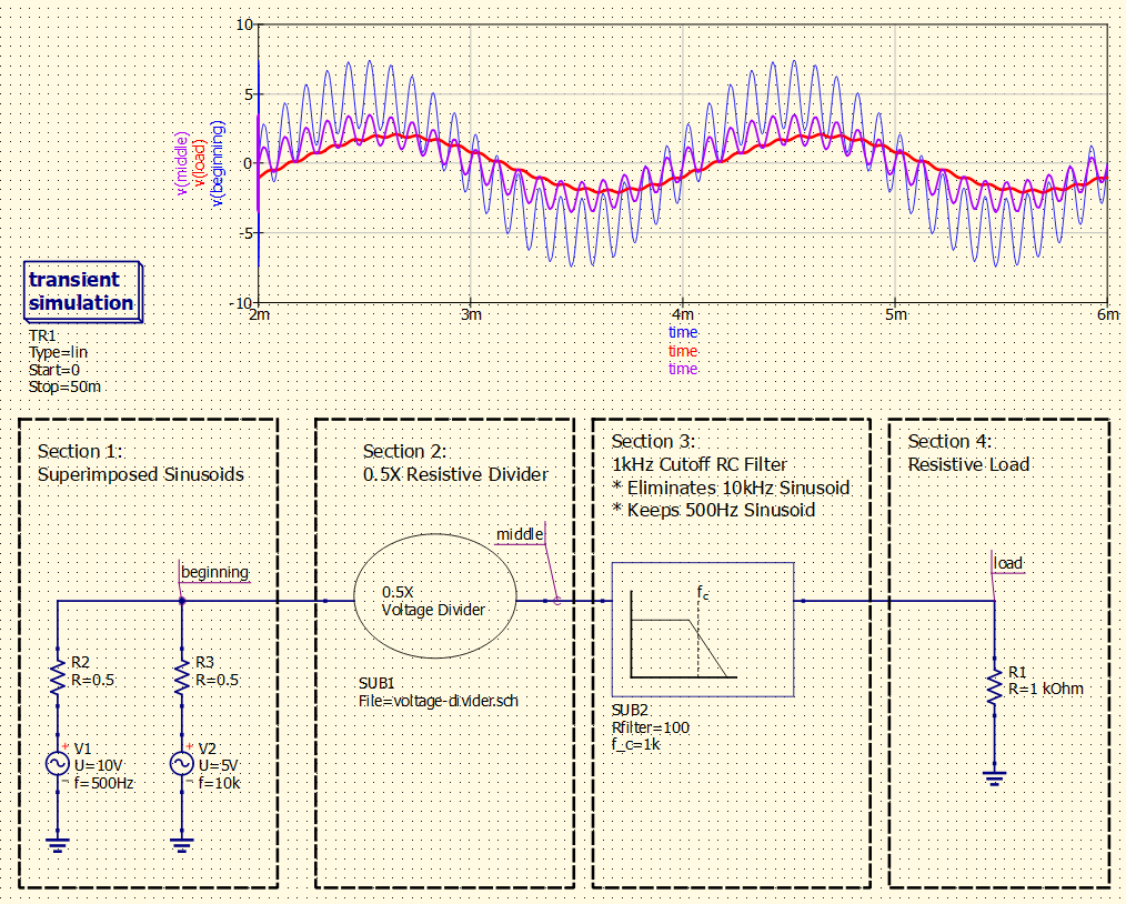
An example of a “hierarchical design” utilizing Qucs-S subcircuits.
The design uses a subcircuit for a resistive voltage divider, and then uses a parameterized subcircuit for a simple RC low-pass filter. Note that the cutoff frequency and resistance values of the filter are set in the top-level context with the f_c and Rfilter parameters, instead of being “hardcoded” into the subcircuit itself.
Subcircuits are simply references to another standard Qucs-S Schematic file (.sch). Any standard .sch can be used as a subcircuit, as long as at least one “port” is added to the schematic.
Warning
This page refers to a different feature from the SPICE .SUBCKT directive! Qucs-S subcircuits facilitate hierarchical designs using the standard Qucs-S schematic editor, it is unrelated to the SPICE .SUBCKT feature.
Preparing a Schematic for use as a Subcircuit
The standard Qucs-S schematic editing tools are also used when creating subcircuits (since subcircuits are really just standard .sch files being referenced in another schematic). However, there are a few steps to take when preparing a circuit to be used as a subcircuit in a larger schematic.
You MUST create at least one Subcircuit Port. This is your circuit’s interface to higher-level schematic files - it is a bidirectional component that allows you to pass signals in and out of your subcircuit. Note that it is NOT necessary to create a port for Ground.
Optionally, you can create a custom symbol for your circuit. Qucs-S will automatically generate a simple symbol, so this is not a requirement, but it usually improves the usability and readability of your schematic.
Optionally, you may add parameters to your subcircuit. Qucs-S allows you to pass parameters through into an instance of your subcircuit, from the parent context. This can be useful when reusing a common design multiple times, with slight variations.
Below is a diagram showing the underlying .sch files, and their schematics and custom symbols, for the voltage divider/RC filter example from earlier in this tutorial.
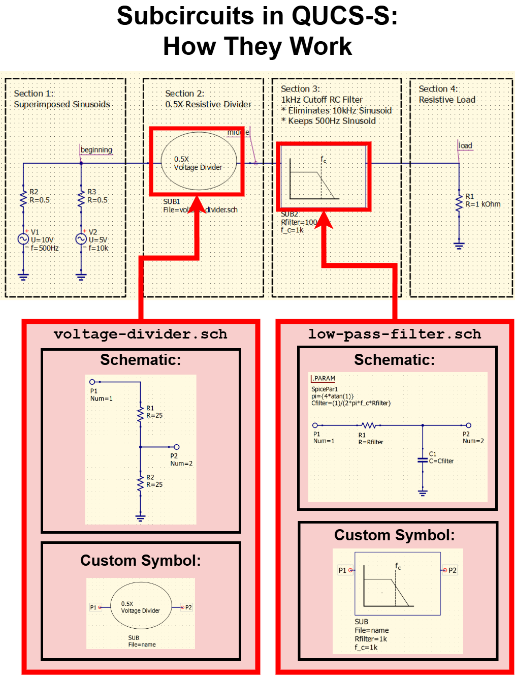
A diagram showing the underlying files, circuits, and custom symbols involved in the voltage divider/RC filter example.
Creating Ports
Any Qucs-S .sch schematic file can be used as a subcircuit, as long as at least one Subcircuit Port is added (creating an externally-accessible interface). This component can be accessed from two places:
The Lumped Components section of the Components tab.
The quick access symbol toolbar at the top of the Qucs-S window.
As an example, we can create a simple RC filter, with an input and output port. This makes it possible to use it as a subcircuit in another schematic. The figure below shows the filter with the necessary Subcircuit Ports.
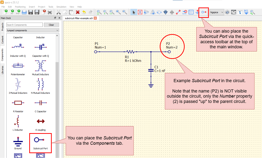
Using Subcircuit Ports to make a schematic usable as a subcircuit.
Note that all Subcircuit Ports have a Number attribute, which is exposed “externally” (when your circuit is used as a subcircuit). The numbers are auto-generated upon placement of the component, but they can be manually edited after the fact through the Properties dialog. This can be useful when creating a subcircuit to mimic an off-the-shelf device or integrated circuit, since the pin numbers can be edited to match the real hardware.
The port name (e.g. P1, P2, etc) is NOT exposed externally. However, if you wish to use text to label a subcircuit port, you can add arbitrary text when creating a custom symbol for your circuit.
Tip
It is not necessary to create a Subcircuit Port for your main ground. The standard Ground component is considered one single net across the entire simulation; it automatically crosses the boundaries of a subcircuit.
Customizing a Schematic’s Symbol
When used as a subcircuit, a Qucs-S schematic file (.sch) does not show its entire contents on the parent schematic page where it’s referenced. Instead, it exposes a symbol to represent it. If you do not intervene, Qucs-S will automatically generate a simple rectangular symbol, and distribute the Subcircuit Ports across it, as shown in the example below.
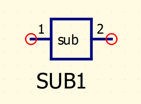
Example of a subcircuit symbol generated automatically by Qucs-S. These symbols can be customized to enhance readability and clarity.
The simulation will work using the default auto-generated symbol, but a symbol like this is not very clear. It’s difficult to tell what the subcircuit’s function is in the parent schematic. For this reason, Qucs-S allows you to customize the symbol that any schematic (.sch) exposes when used as a subcircuit.
To access the symbol editor, navigate to your subcircuit .sch file in the editor, and navigate to File > Edit Circuit Symbol. You can also press the F9 keyboard shortcut. This will open the editor for this schematic’s symbol. From this window, you can use the normal page editing tools and the graphics components in the Paintings section of the Components tab to customize your circuit symbol.
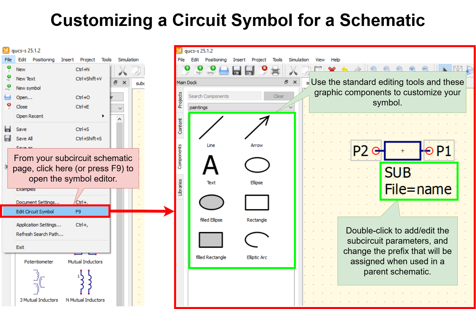
Navigating to the Circuit Symbol Editor. This allows you to customize the symbol that a schematic (.sch) file exposes when used as a Subcircuit in a parent schematic.
Parameterizing a Subcircuit
Creating and Modifying Parameters
When using subcircuits, it is also possible to pass parameters from the parent circuit into the subcircuit. These parameters can be integrated with the standard parameterization features in QUCS-S, such as the SPICE .PARAM block commonly used with ngspice.
To create new parameters that your circuit will expose when used as a subcircuit, visit the “Edit Circuit Symbol” dialog (F9 hotkey). Then right-click the text underneath your circuit symbol, and choose “Edit Properties” as shown in the image below.
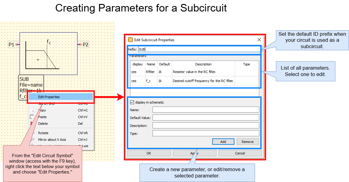
How to add or modify parameters for your subcircuit to expose to a parent circuit.
Each parameter has 5 properties:
display: Set to “Yes” to show this parameter by default on your parent schematic page.Name: This is the actual parameter/variable name, which you’ll need to reference inside your subcircuit.Default: The default value for this parameter when your subcircuit is initially placed. Of course, you can modify the actual value for each instance of the subcircuit that you place in a parent schematic, this is simply the default/initial value.Description: A human-readable, arbitrary comment describing your parameter. This is visible when setting the parameter from a parent circuit. Set this to whatever you like, there is no specific format required.Type: This is an additional human-readable, arbitrary comment. You don’t have to use it, but it may be useful to note the intended units for a parameter.
All the parameters created here are automatically made available within the subcircuit. The method for accessing them varies slightly depending on simulation backend:
For Qucsator-based simulations, they are accessed in the same way as standard Qucsator Equation variables (see the relevant content for more details on syntax).
For SPICE-based simulations (ngspice, Xyce, SpiceOpus), they are accessed in the same way as
.PARAMvariables (see the relevant content for more details on syntax).
Example Parameterized Subcircuit
As an example, you might wish to create an RC low-pass filter as a subcircuit, and parameterize the series resistance and the desired cutoff frequency. Then, inside the subcircuit, a standard SPICE .PARAM component can be used to select the capacitor’s value automatically, based on the desired cutoff frequency. An example of such a circuit is shown below.
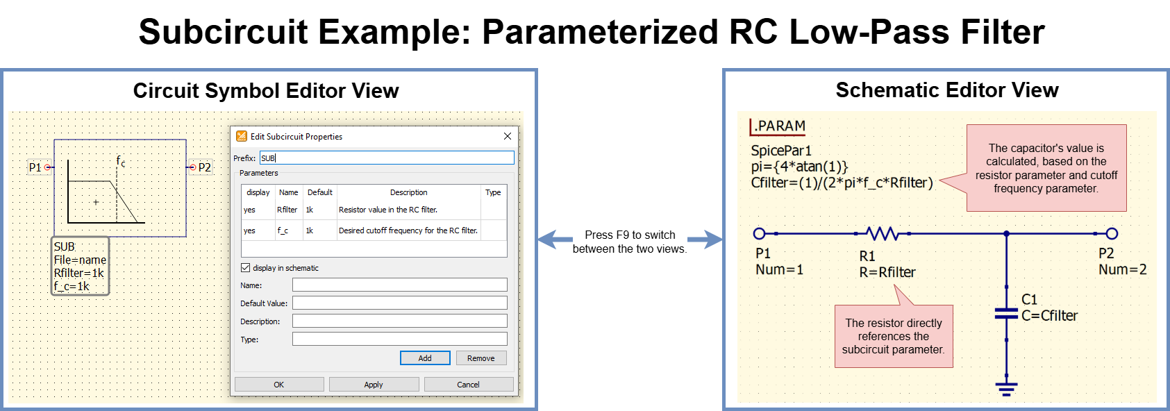
An example use case for subcircuit parameters. This example shows an RC filter, which has been parameterized to allow passing in a desired series resistance and a desired cutoff frequency from the parent circuit. The capacitor’s value is calculated based on the resistance and the desired cutoff frequency.
Using a Subcircuit in a Schematic
Once you have prepared your .sch file for use as a subcircuit, there are two ways to place it into a parent schematic as a subcircuit. See the sections below.
Placing a Subcircuit from the Content tab (recommended)
If the file you want to use as a subcircuit is inside the same QUCS-S project folder as your parent schematic, you can place it conveniently from the Content tab (see the UI overview if you are unsure where this is.)
To do this, simply navigate to the Content tab, and find the circuit you wish to place as a subcircuit under the Schematics dropdown. Right-click it, choose “Insert”, then left-click anywhere on your schematic page to place it as a subcircuit. You can place multiple instances if you like - press the ESC key when you are done placing instances of the subcircuit.
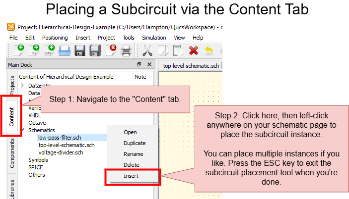
Accessing and placing a Subcircuit on a Qucs-S schematic page, via the Content tab.
Placing a Subcircuit with a Custom File Path
If the file you want to use as a subcircuit is NOT inside the same QUCS-S Project folder as your parent schematic, use this method to place it, since it will allow to manually specify any arbitrary path to the subcircuit file.
Navigate to the File Components section of the Components tab, and place the Subcircuit component on your schematic page. When it is first placed, it will not perform any function, since it has not been linked to a QUCS-S Schematic (.sch) file yet.
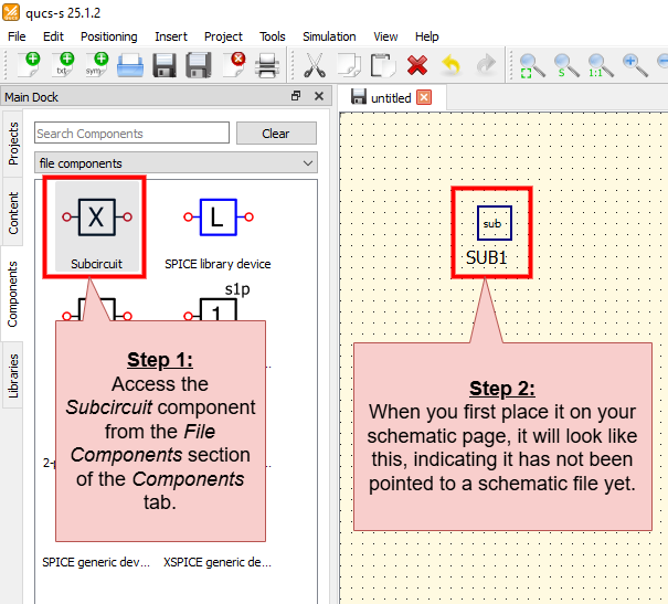
Accessing and placing a Subcircuit on a Qucs-S schematic page, without a particular .sch file specified yet.
Once the Subcircuit component is placed, right-click it and choose “Edit Properties”. You can select your desired Schematic (.sch) file from within the “Edit Properties” window, as shown in the screenshots below.
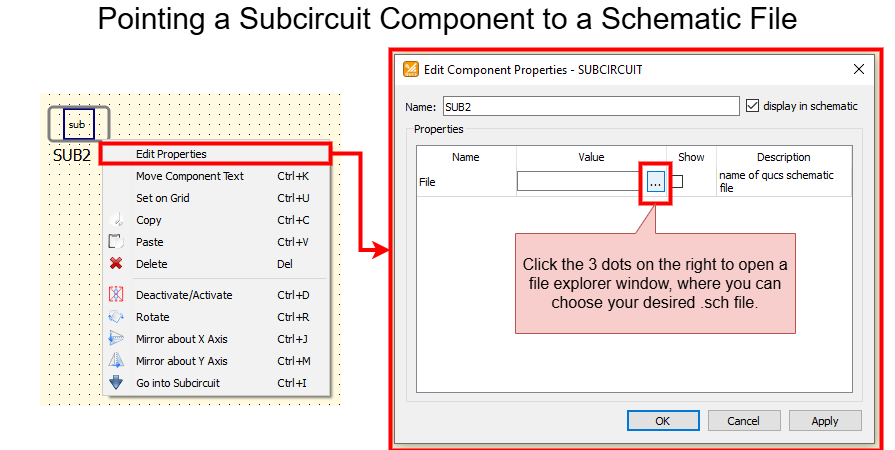
Pointing a newly-placed Subcircuit component to a schematic file.
After you select a .sch file, the Subcircuit symbol will change to the symbol specified by your file, and any necessary parameters and circuit ports will appear on the page. At that point, the Subcircuit is ready to be used in your design.
Manipulating Parameters of a Subcircuit Instance
After placing an instance of your subcircuit in a parent schematic, simply right-click the component and choose “Edit Properties” to modify the parameters (as shown in the figure below). Note that the parameter names, descriptions, default values, and default visibility settings are all passed up from inside the subcircuit.
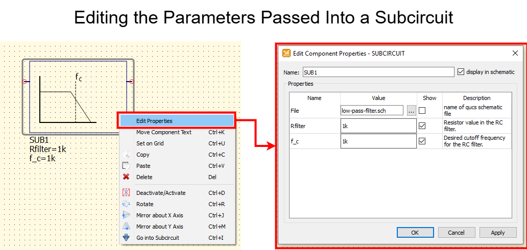
An example of how to edit the parameters for an instance of a subcircuit, using the “Edit Properties” dialog from within the parent schematic.