Using SPICE Complex Device Models (.SUBCKT Directive)
Introduction
What is the SPICE .SUBCKT Directive?
Warning
Although their names are similar, the SPICE .SUBCKT directive is different from the [QUCS-S Subcircuits] feature!
The SPICE netlist syntax supports subcircuits/hierarchical designs using the .SUBCKT directive.
Every .SUBCKT block has a name, and exposes some number of “external ports”, each with their own integer “port number”. The purpose of each port is often described in the comments of the SPICE netlist file containing the .SUBCKT.
In contrast to the .MODEL directive, which can only adjust the parameters of standard SPICE device models, a .SUBCKT can contain an arbitrary circuit with any of the standard SPICE devices, including transistors and diodes with their own customized .MODEL parameters. .SUBCKTs can also be nested to model more complex devices.
How are .SUBCKT models distributed?
Most electronics manufacturers will provide SPICE .SUBCKT models for their integrated circuits (ICs), and even sometimes for complete pluggable electronic modules. These models are simply textual SPICE netlists containing the necessary .SUBCKT and other directives, typically with the .lib or .cir extension.
Tip
Many commercial SPICE-based simulators (such as LTspice or PSPICE) include their own extensions to the standard SPICE netlist syntax.
Unfortunately, some manufacturer-provided SPICE models are designed specifically for one of these commercial simulators, and utilize some of their non-standard syntax.
If you try to run these models in QUCS-S (with ngspice/Xyce/SpiceOpus backends), you may receive some cryptic SPICE netlist syntax errors. You can often get around this problem by enabling one of the “Compatibility Modes” in your chosen simulation backend.
Example Model
Below is a model for the popular LM358 operational amplifier.
Note that the identifier of the .SUBCKT directive is LM358, and the exposed ports are 1, 2, 99, 50, and 28. The functions of each port are described in the comments above the .SUBCKT directive.
*//////////////////////////////////////////////////////////////////////
* (C) National Semiconductor, Inc.
* Models developed and under copyright by:
* National Semiconductor, Inc.

*/////////////////////////////////////////////////////////////////////
* Legal Notice: This material is intended for free software support.
* The file may be copied, and distributed; however, reselling the
*  material is illegal

*////////////////////////////////////////////////////////////////////
* For ordering or technical information on these models, contact:
* National Semiconductor's Customer Response Center
*                 7:00 A.M.--7:00 P.M.  U.S. Central Time
*                                (800) 272-9959
* For Applications support, contact the Internet address:
*  amps-apps@galaxy.nsc.com

*//////////////////////////////////////////////////////////
*LM358 DUAL OPERATIONAL AMPLIFIER MACRO-MODEL
*//////////////////////////////////////////////////////////
*
* connections:      non-inverting input
*                   |   inverting input
*                   |   |   positive power supply
*                   |   |   |   negative power supply
*                   |   |   |   |   output
*                   |   |   |   |   |
*                   |   |   |   |   |
.SUBCKT LM358       1   2  99  50  28
*
*Features:
*Eliminates need for dual supplies
*Large DC voltage gain =             100dB
*High bandwidth =                     1MHz
*Low input offset voltage =            2mV
*Wide supply range =       +-1.5V to +-16V
*
*NOTE: Model is for single device only and simulated
*      supply current is 1/2 of total device current.
*      Output crossover distortion with dual supplies
*      is not modeled.
*
****************INPUT STAGE**************
*
IOS 2 1 5N
*^Input offset current
R1 1 3 500K
R2 3 2 500K
I1 99 4 100U
R3 5 50 517
R4 6 50 517
Q1 5 2 4 QX
Q2 6 7 4 QX
*Fp2=1.2 MHz
C4 5 6 128.27P
*
***********COMMON MODE EFFECT***********
*
I2 99 50 75U
*^Quiescent supply current
EOS 7 1 POLY(1) 16 49 2E-3 1
*Input offset voltage.^
R8 99 49 60K
R9 49 50 60K
*
*********OUTPUT VOLTAGE LIMITING********
V2 99 8 1.63
D1 9 8 DX
D2 10 9 DX
V3 10 50 .635
*
**************SECOND STAGE**************
*
EH 99 98 99 49 1
G1 98 9 POLY(1) 5 6 0 9.8772E-4 0 .3459
*Fp1=7.86 Hz
R5 98 9 101.2433MEG
C3 98 9 200P
*
***************POLE STAGE***************
*
*Fp=2 MHz
G3 98 15 9 49 1E-6
R12 98 15 1MEG
C5 98 15 7.9577E-14
*
*********COMMON-MODE ZERO STAGE*********
*
*Fpcm=10 KHz
G4 98 16 3 49 5.6234E-8
L2 98 17 15.9M
R13 17 16 1K
*
**************OUTPUT STAGE**************
*
F6 50 99 POLY(1) V6 300U 1
E1 99 23 99 15 1
R16 24 23 17.5
D5 26 24 DX
V6 26 22 .63V
R17 23 25 17.5
D6 25 27 DX
V7 22 27 .63V
V5 22 21 0.27V
D4 21 15 DX
V4 20 22 0.27V
D3 15 20 DX
L3 22 28 500P
RL3 22 28 100K
*
***************MODELS USED**************
*
.MODEL DX D(IS=1E-15)
.MODEL QX PNP(BF=1.111E3)
*
.ENDS
*$
Importing .SUBCKT Models with “SPICE Library Device” (recommended)
Warning
This section depends on a feature that was not added until QUCS-S v24.3.0 (released July 2024).
If you are using a QUCS-S version older than v24.3.0, this feature is not available! You will need to use the more manual method described in the next section.
With .SUBCKT-based models, you can use the SPICE Library Device component to quickly import your model and select a symbol. This component includes templates for common electronics symbols, and the option to input a custom symbol file if you desire.
To get started, navigate to the File Components section of the Components tab, and place a SPICE Library Device on your schematic. Initially, the symbol will be a simple square with no pins, as shown in the screenshot below.

Annotated screenshot showing how to place a SPICE Library Device on a schematic. Note that a new instance of this component will appear as a simple square symbol with no terminals, until you configure it with a real SPICE model and choose a symbol.
To configure the SPICE Library Device, double-click the symbol to open its Properties dialog. Then:
Select your SPICE model file (typically
.libextension).If your file contains multiple
.SUBCKTdirectives, use the bottom right section of the dialog to select the appropriate one.Configure a symbol. Select from the following options:
Automatic Symbol: This will generate a rectangular symbol, with pin names matching the SPICE
.SUBCKT. This is usually a good fit for complex integrated circuits which are hard to describe with traditional symbols.Symbol from Template: This will let you choose from a list of common electronics symbols, including op-amps, transistors, logic gates, and diodes. You can configure the mapping between symbol pins and SPICE
.SUBCKTpins in the bottom left portion of the window.Symbol from File: If the previous options are insufficient, you can specify a custom QUCS-S Symbol file (
.symextension). See the next section for instructions on how to create such a file.
Map your symbol’s pins to the appropriate pins in your
.SUBCKTmodel. It is often necessary to read the comments in the SPICE netlist to determine the function of each pin, so a preview of the SPICE model is provided in the bottom right of the window for your convenience.(Optional) If your model accepts parameters, pass the appropriate parameters in using the “Component Parameters” text box.
Not all models require parameters. You can tell if your
.SUBCKTaccepts parameters by looking for parameter definitions right after the main.SUBCKT portname1 portname2portion of the SPICE file. See the relevant sections of the ngspice manual for examples of a.SUBCKTwith parameters.The standard SPICE parameter syntax applies. See the section on Equations and Parameters for more information.
The annotated screenshot below highlights each of the major sections of the configuration dialog, with an example LM358 op-amp model selected.

Annotated screenshot showing the configuration options for a SPICE Library Device, using the common LM358 op-amp as an example.
In the case of the LM358, the opamp5t symbol in the “Use Symbol from Template” feature is a good fit. After mapping the terminals and clicking OK to exit the SPICE Library Device configuration dialog, the schematic symbol now looks like an op-amp, and the device is usable in the schematic.
The SPICE Library Device from the previous examples, after configuring with the LM358 model file, appropriate symbol, and appropriate symbol pin mapping. This device is now usable within the QUCS-S schematic.
Creating a Custom Symbol File
In some cases, you may wish to create a custom symbol for a SPICE Library Device instead of relying on the auto-generated symbols or the pre-made templates. To do this, create a new Symbol File using the button on the toolbar. This will open a new document, as shown below, with a default square symbol (the same as the default symbol for a QUCS-S subcircuit).
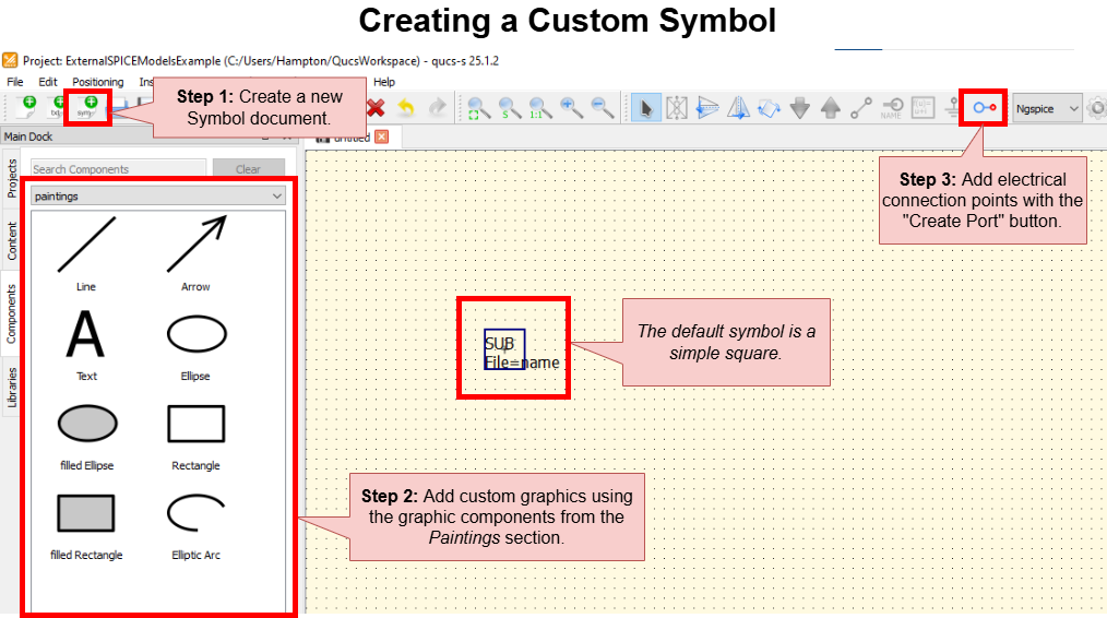
Creating a custom symbol document in QUCS-S. These symbols can be used with SPICE library devices (among other use cases).
Use the “Paintings” components to create the graphics of your symbol. To add electrical ports, use the Insert Port button, just like when you edit a QUCS-S subcircuit symbol.
When you are happy with the symbol, save it, and return to your main schematic. Open the configuration for your SPICE Library Device, and point it to your new custom symbol file. See the earlier section on configuring SPICE Library Devices for more details.
Importing .SUBCKT Models with “SPICE File Component”
Warning
If you are using QUCS-S version v24.3.0 (released July 2024) or later, see the previous section for a much more efficient method of using .SUBCKT models! The method described below will still work in newer versions of QUCS-S, but it generally offers no advantage over the new SPICE Library Device method.
If you are using a version of QUCS-S prior to v24.3.0, the method described in this section is the only method of using .SUBCKT models.
Part 1: Using “SPICE File Component”
The first part of the process is to place a SPICE File Component in your schematic. Generally, you’ll want to create a new, empty schematic (.sch) for this purpose, since you’ll need to use this schematic as a subcircuit if you wish to customize the symbol.
Ensure your SPICE model file is saved in a convenient location on your filesystem. In this example, it’s saved in
/home/vvk/LM358.cir.Using the File Components section of the Components tab, place a SPICE File Component on your schematic page. Once you place it, it should appear as a square symbol with no pins.
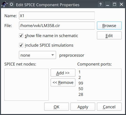
Double-click the newly-placed SPICE File Component symbol to open its Component Properties dialog. Specify the path to your SPICE model file by clicking the Browse button.
Once you select your model, you’ll see a list of the model’s ports appear in the Component Properties dialog. In most cases, you’ll want to simply add all the model’s ports to the “Component Ports” list, which makes them appear in the QUCS-S symbol. After completing steps 1-4, your Component Properties dialog should look like the screenshot below.
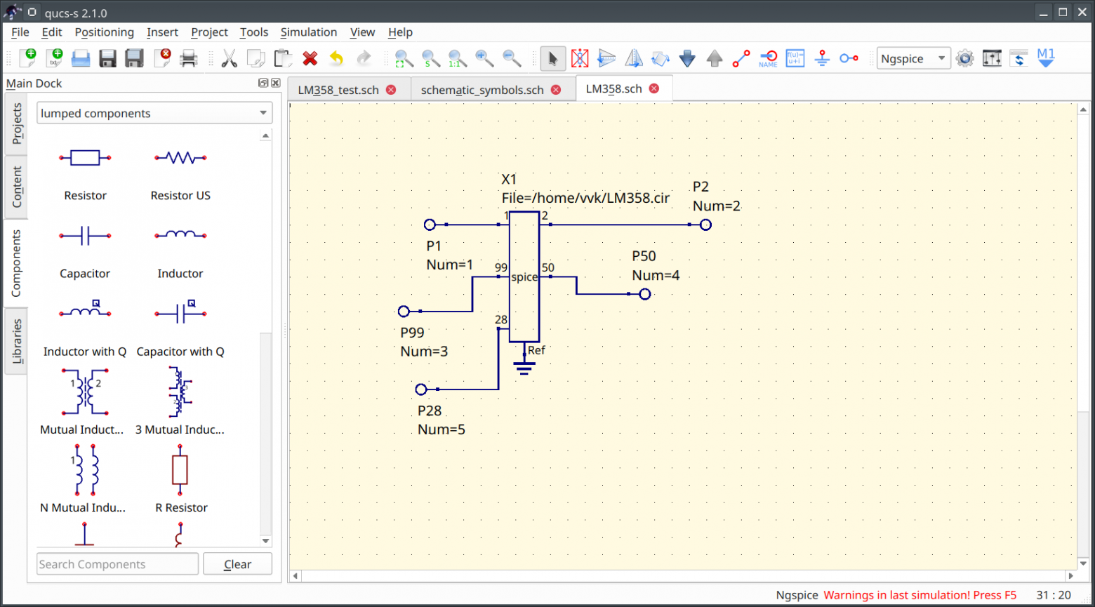
Once the component is configured, click OK to exit. The symbol should have changed - it should now be showing all the terminals you added to the “Component Ports” list. At this point, the model is usable in simulations. A simple DC operating point simulation has been performed in the screenshot below, which confirms the model is functioning correctly.

At this point, the model is usable for simulations. However, if you wish to create a customized symbol, continue on to the next section.
Part 2: Custom Symbol by Wrapping in a QUCS-S Subcircuit
The SPICE File Component offers no direct provision for customizing its symbol. It simply auto-generates a basic rectangular symbol. To create a custom symbol, the SPICE File Component will need to be wrapped in a QUCS-S Subcircuit, and then the subcircuit’s symbol can be customized to suit your needs.
To do this, first ensure your SPICE File Component is the only component on your schematic. Then add the necessary QUCS-S Ports for it to function as a subcircuit. The end result will be something like the screenshot below.
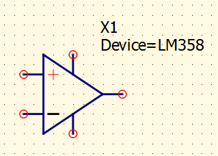
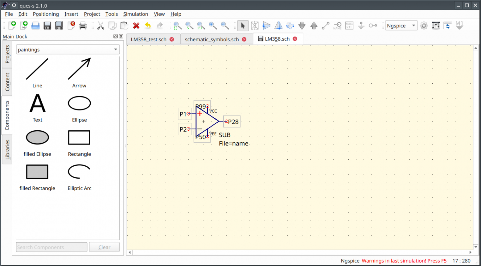
After doing that, press F9 to enter the symbol editor for your .sch file. Draw your desired symbol here (see the subcircuit documentation for more details on how to do this). An example op-amp symbol is shown below.
After doing that, simply place an instance of your new subcircuit anywhere you want to use your SPICE model. It will appear with your custom symbol, and under the hood it will still be referencing the SPICE model you configured in the SPICE File Component. An example simulation using this method is shown below.
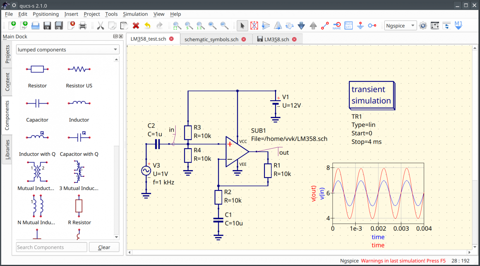
An example of a simulation using an external SPICE model, achieved with the “SPICE File Component wrapped in a QUCS-S subcircuit” method.