Digital Simulation
Warning
This section of the documentation would benefit from additional detail. Contributions are welcome! Please see this GitHub issue if you wish to contribute.
Qucs-S supports a number of digital devices, which can be found in the Digital Components component group. This includes devices such as:
Logic gates
Inverters
Buffers
Flip Flops (D-, JK-, and T-)
Digital Sources
These devices can be used in two ways:
As simplified, ideal digital devices in standard analog circuits. We’ll call this “Mixed-Signal Digital Simulation.”
As digital devices in a pure-digital simulation environment (using Verilog or VHDL backends). We’ll call this “Pure-Digital Simulation.”
Mixed-Signal Digital Simulation
It’s possible to add devices from the Digital Components group to standard analog circuit. In the case of the ngspice simulation backend, these devices operate using XSPICE models. This is a convenient way to simulate ideal digital devices, without having to obtain SPICE models for a specific real-world logic gate IC.
Warning
In addition to placing digital components on your schematic, you must also set the logic voltage for the whole circuit, using the SPICE parameter vcc. (Use the .PARAM block from the Spice Netlist Sections component group to do this.)
This also means that all digital devices in your circuit must share the same logic voltage! You cannot utilize this simulation technique with multiple logic power busses, or in a “level shifting” situation.
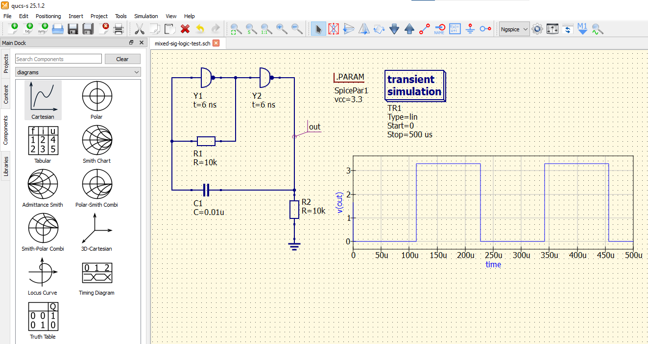
In this example, an oscillator is being simulated using inverters. The inverters have their delay time set at 6ns, which contributes to the oscillator behavior. This simulation is done in Transient mode, with the ngspice simulation backend (although it may work in other backends as well).
Pure-Digital Simulation
Qucs-S also has the ability to utilize entirely-digital simulation backends (VHDL or Verilog). This feature does NOT facilitate mixing analog and digital components into a single circuit.
Warning
To perform these simulations, you must install the iverilog or ghdl backend. See Installing Simulation Backends for more information.
To start a digital simulation, place the Digital Simulation component on your schematic page. This block has 3 parameters:
Simulation Type: The type of simulation to run. Choose Truth Table or TimeList (timing diagram).
Time: The duration of the simulation.
Model: The simulation backend/netlist format to use (Verilog or VHDL).
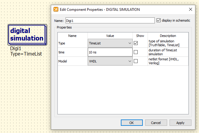
The Digital Simulation block, and the configurable parameters in its Properties.
Note
If the Digital Simulation block is placed on your schematic page, Qucs-S will run the digital simulation regardless of which of the simulation backends is selected at the top of the window. In other words, you do NOT need to select GHDL or IVerilog in the same place where you would select ngspice, Xyce, etc. Simply place the Digital Simulation block on your schematic page.
The example below shows a Digital Simulation in TimeList (Timing Diagram) mode, simulating a 2-bit decoder/demultiplexer.
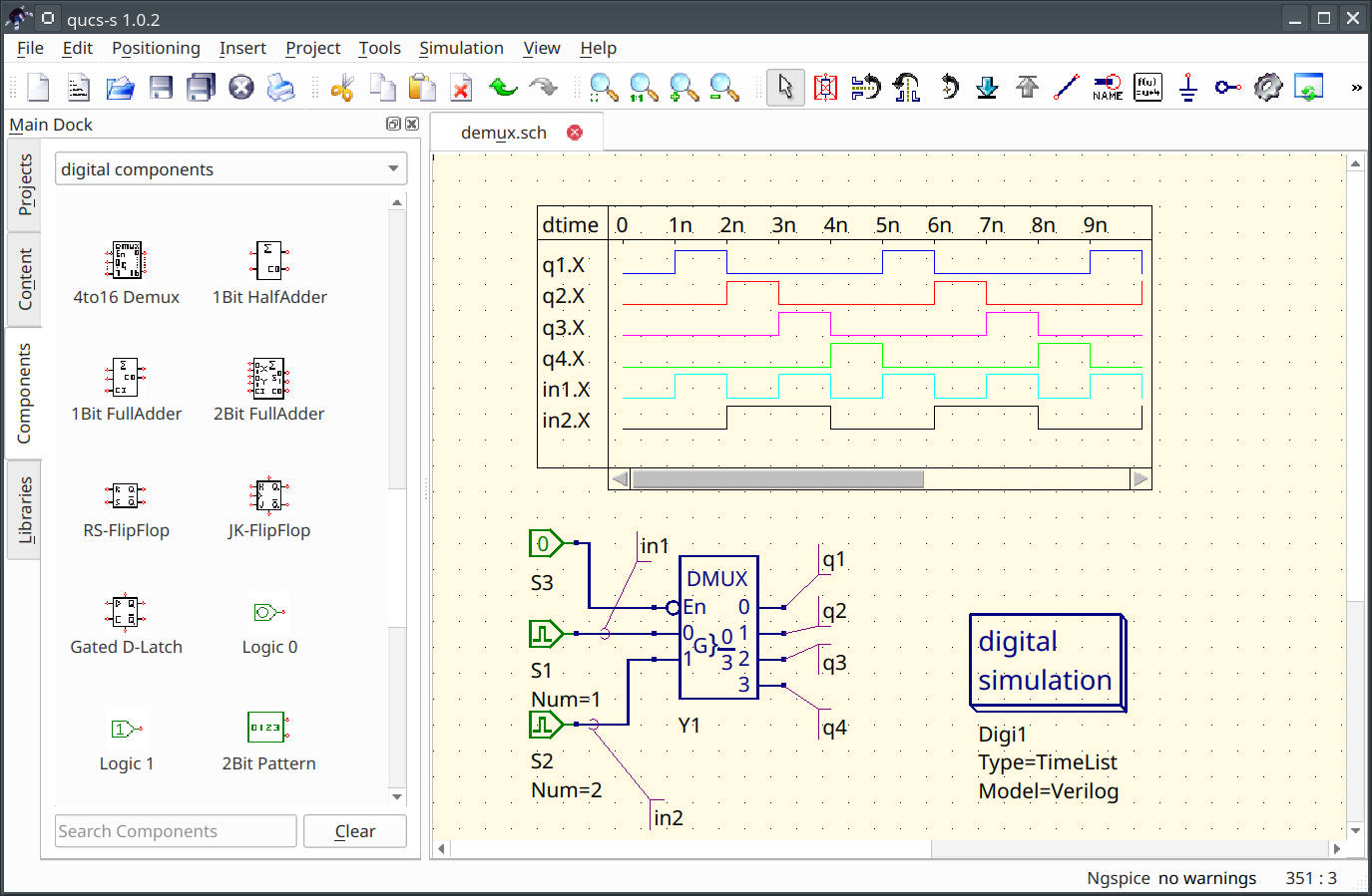
Simulation of a 2-bit decoder/demultiplexer, in the TimeList (timing diagram) mode, using the Verilog backend.