Parameter Sweep Simulations
Often in circuit simulation, it is useful to repeat a similar simulation while varying one or more parameters. This makes it easy to see how specific parameters affect your circuit’s behavior.
Tip
You may wish to interactively modify circuit parameters using sliders, rather than defining a range ahead of time and performing a traditional sweep. This is possible using the Tuning Mode feature!
Qucs-S can support this type of simulation using the Parameter Sweep Simulation. This component can sweep the value of a passive component (resistor, inductor, capacitor, or source), or with some additional configuration, can sweep a custom parameter. It accepts an existing Simulation Component as an input, and the Parameter Sweep will repeat that simulation for all the values of the swept parameter.
Warning
The standard Parameter Sweep Simulation can only sweep the values of passive components! (This includes resistors, capacitors, inductors, and voltage sources.) On its own, it cannot define and sweep an arbitrary variable in your schematic.
Defining and sweeping arbitrary variables is possible for some simulation backends, but requires additional steps. See the section below on Sweeping Arbitrary Parameters to learn more.
An example of this Simulation Component is shown in the figure below. It’s set up to sweep a resistor R1’s value, and repeat the Transient Simulation TR1 for each iteration of R1.

An example of a Parameter Sweep Simulation Component placed on a schematic page. In this case, it is sweeping the value of a resistor (off-screen) being used in a Transient Simulation (TR1). Note the flowchart showing the Parameter Sweep’s logic.
The Parameter Sweep Simulation accepts 6 major inputs:
Sim: This is the ID of the simulation which should be run inside the sweep “loop.” For example, in the figure above,
TR1is used, meaning the Parameter Sweep will run a new instance of theTR1Transient Simulation for each swept value of ResistorR1.Type: The mathematical distribution of the swept parameter. This can be linear (
lin), logarithmic (log), or a discrete list of values defined by the user (list).Param: The device whose value is to be swept. Typically, this must be a passive component (resistor/capacitor/inductor/source). With additional configuration, some simulation backends may be able to sweep arbitrary variables, rather than being limited to only passive component values. See the section on Custom Parameter Sweeps to learn more.
Start: Defines the start point for the swept device or parameter.
Stop: Defines the end point for the swept device or parameter.
Points: Defines the number of points in the sweep (between the Start and Stop values).
Sweeping Passive Component Values (Device Sweeps)
The most basic way to utilize the Parameter Sweep Simulation Component is to sweep the value of a passive device (resistor, capacitor, inductor, or source). This is possible using just the Simulation Component itself, no additional SPICE declarations or extra steps needed.
Example: Capacitor Charging (Before Sweep)
Before adding a sweep, let’s consider an example circuit without a sweep. In this circuit, a voltage source is being used to charge a capacitor. At the start of the simulation, the capacitor’s voltage is zero. Then, the voltage source turns on and begins charging the capacitor. We can see the capacitor’s charge voltage increase on the Cartesian diagram as it charges.

A simple capacitor, which is being charged through a resistor. Using a Transient simulation, we can see the capacitor’s voltage increase over time, as it is charged by the voltage source.
In the next section, we’ll look at how a Device Sweep could be performed to give more insight into this circuit.
Example: Capacitor Charging (With Device Sweep Added)
In the previous example, we might wish to compare how the capacitor charges as we vary resistor R1 (allowing more or less current to flow into the capacitor). This can be done by adding a Parameter Sweep simulation, as shown in the figure below.
Warning
Note that the Parameter Sweep should be added in addition to the existing simulation. Do not delete or deactivate your original simulation component when you add a Sweep. You must retain your original “unswept” simulation (regardless of what type of simulation it may be), since the Parameter Sweep will reference it.
In this new example, 4 Transient Simulations are run, with 4 different values of resistor R1 (200 Ohm, 800 Ohm, 1.4 kOhm, and 2 kOhm). As a result, the 4 distinct capacitor charging curves can be seen on the Cartesian diagram. No modification was required to the diagram’s properties compared to the previous example - the complete set of curves was graphed automatically.

By adding a Parameter Sweep simulation component to the previous example, we can now observe the charging behavior of the capacitor as resistor R1 is varied from 200 Ohms to 2 kOhms, in 600 Ohm increments.
Tip
The value of a voltage source, current source, inductor, or capacitor could also be swept, in the same way as the resistor in the above example.
DC Sweeps
In Qucs-S, a DC Sweep refers to a Parameter Sweep combined with a DC Simulation. This is often useful for determining how a resistor or power supply voltage affects DC bias points.
For example, the circuit below is a simple resistive voltage divider connected to a DC voltage source. A standard DC Simulation can be used to calculate the output voltage of the divider. However, in this example, a Parameter Sweep has been added, sweeping the resistor R1 from 1 kOhm to 4 kOhm.
The resulting output voltage for each value of R1 is displayed in a Table Diagram (although it could just as easily be graphed).

An example of a “DC Sweep”, which combines the Parameter Sweep Simulation with a DC Simulation. In this case, a resistor in a simple voltage divider is swept, and the resulting output voltages are shown in a Table.
Warning
Only resistors and sources can be swept as part of a DC Sweep.
Inductors and capacitors are not considered in DC sweeps (inductors become short-circuits while capacitors become open-circuits). Therefore, these components cannot be swept.
Sweeping custom parameters in a DC Simulation is NOT possible, regardless of simulation backend! Even the .PARAM feature in ngspice (see next section) does not apply to this case - it is simply not possible to sweep anything except a resistor or a source when performing a DC Simulation.
Sweeping Arbitrary Parameters
In the sections above, only passive components and sources were swept. However, when using the ngspice Simulation Backend, it is possible to use a SPICE .PARAM command to define and sweep any arbitrary parameter within a circuit. When using this method, you are no longer limited to just passive components and sources.
Warning
This section only applies to recent versions of ngspice! ngspice prior to version 30 (released in 2018) may not support this feature. This tactic also does not apply to other available simulation backends.
To do this, a .PARAM directive must be added to the SPICE netlist. To do this in Qucs-S, visit the “SPICE netlist sections” category of the Components tab. Add a .PARAM Section component to your schematic page (circled in the figure below).
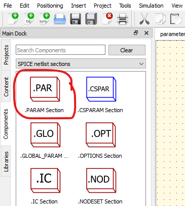
To add a .PARAM directive to your SPICE netlist, place a .PARAM Section component on your schematic page.
Example: Sweeping Filter Cutoff Frequency
For example, the circuit below is a simple RC filter, being fed with an AC voltage source. It has an AC Simulation, to characterize the frequency response of the filter.
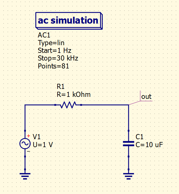
Simple RC filter example, with an AC Simulation command.
Recall that for an RC filter, the “-3dB cutoff frequency” can be calculated with \(f_{cutoff} = \frac{1}{2\pi RC}\).
It’s possible to calculate the necessary capacitor for a given cutoff frequency by rearranging the equation, yielding \(C = \frac{1}{2\pi Rf_{cutoff}}\).
For the sake of example, let’s utilize the .PARAM feature to define C1’s capacitance in terms of the filter’s cutoff frequency (\(f_{cutoff}\)), and then sweep \(f_{cutoff}\) with a Parameter Sweep simulation. This will show the frequency response of RC filters across a number of cutoff frequencies.
To do this, we’ll perform the following modifications to the circuit:
Add a .PARAM Section to the schematic, and define relevant variables. You can define as many variables as you like in a single .PARAM Section component - you do not need to add multiple components to the page to define multiple variables.
Modify the circuit to reference our new parameters. In this case, we will modify
R1andC1. Be sure to encapsulate with{and}so the parameters and math is parsed properly by the simulator!Add a Parameter Sweep component, and select the variable defined in the .PARAM Section as the sweep parameter.
Tip
There is no built-in Pi constant in ngspice. To easily utilize Pi ( \(\pi\) ) in your schematics, put the following into a .PARAM Section:
pi=4*atan(1)
This allows you to use pi in your schematics.
Warning
You must enclose parameters and math operations in curly braces, or ngspice will not parse them correctly!
After the modifications, and the addition of a Cartesian diagram to graph the results, the circuit looks like this:

RC filter example, with capacitance defined in terms of cutoff frequency. The cutoff frequency is parameterized (f_cutoff), and swept using a Parameter Sweep. This allows simulation of filters designed for varying cutoff frequencies.
Double Sweeps (aka Nested Sweeps)
You might wish to sweep two parameters instead of just one. This is possible by nesting multiple Parameter Sweeps. Set the first Parameter Sweep up with the Sim property pointing to a normal simulation (for example, a transient simulation). Then, set the second Parameter Sweep up with the Sim property pointing to the first parameter sweep. This allows you to sweep multiple parameters, and see how the circuit’s performance varies.
For example, if you want to graph the \(V_{CE}\) vs \(I_{c}\) curves of a transistor, you’ll need to sweep two parameters. First, you need to sweep the collector-emitter voltage (\(V_{CE}\)), and then repeat that sweep for a different value of base current - rinse and repeat. This is a great use case for “nested sweeps” in Qucs-S.
An example of how to do this is shown in the figure below. Note that while Parameter Sweep SW1 is sweeping the DC Simulation, Parameter Sweep SW2 is sweeping SW1!

Example of a double/nested sweep, plotting the \(V_{CE}\) vs \(I_{c}\) curves of a transistor.