Interface Overview
This page will introduce you to the basic controls in the Qucs-S user interface.
Main Window Summary
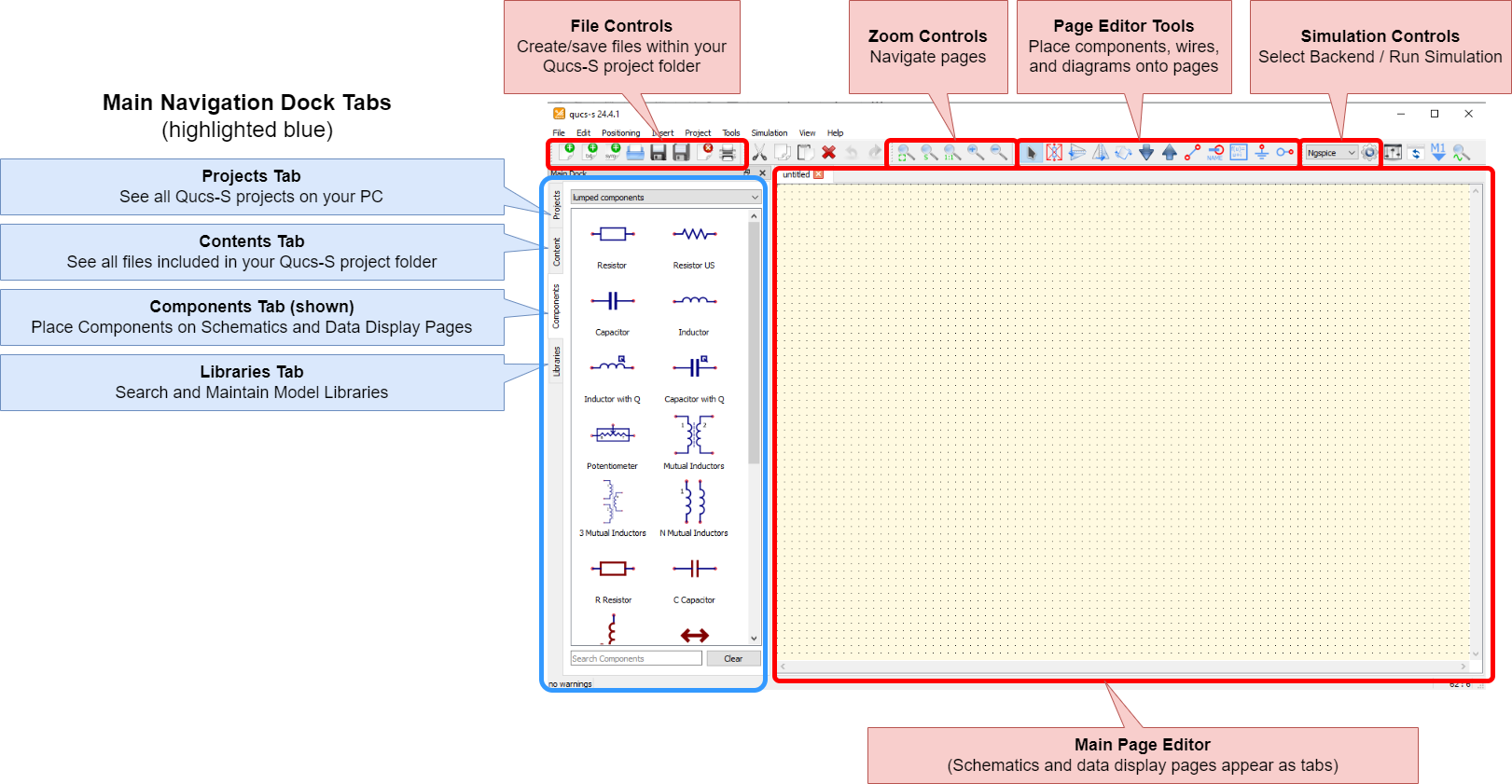
The main Qucs-S window, with the most important controls annotated.
Here are the major controls to be aware of in the main Qucs-S window:
Main Navigation Dock Tabs: These tabs are used to manage your project’s files, and add components and diagrams to your project’s pages. See section below for details.
File Controls: Use these buttons to create and save files (such as schematic pages) within your Qucs-S project.
Zoom Controls: Use these controls to navigate the main page editor.
Page Editor Tools: Use these buttons to place components and wires on your pages, and modify their position/orientation.
Simulation Controls: Select your simulation backend using the drop-down menu. Then push the gear icon to run your simulation.
Main Page Editor: A tabbed navigation area in the center of the window. Each schematic page, data display page, and other resource in your Qucs-S project will appear as a tab here.
Main Navigation Dock Tabs
The left portion of the Qucs-S window contains the main navigation dock. It can be repositioned at will, but it defaults to the left side of the window.
It contains 4 tabs, described below (from top to bottom).
Projects Tab
This tab is used to choose a Qucs-S project to work in. It lists all the Qucs-S projects stored in the default directory (Typically, C:\Users\John Doe\QucsWorkspace or /home/johndoe/QucsWorkspace).
See the Understanding File Structure page for more information on how Qucs-S projects are stored.
Warning
Qucs-S can only have one active project at a time. In other words, you cannot have a schematic open from project A, and also open a schematic from project B. If you try to do this, Qucs-S will simply close the first project’s files.
This tab allows a few basic tasks:
To activate a project, either double-click it, or single-click it and choose “Open”. Upon activating the project, you’ll be taken to the Contents tab, summarizing that project.
To create a new project, click the “New” button.
To delete a project, click the “Delete” button.
If your Qucs-S Home Directory contains subfolders to organize your projects, you can navigate the subfolders within the Projects tab by double-clicking (much like a typical file explorer view).
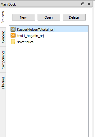
The Qucs-S Projects tab, in the main navigation dock.
Contents Tab
The Contents tab serves as an organized summary of all the files in your active project. It is akin to a file explorer within your Qucs-S project folder.
To open a document within your project, double-click on it within the Contents tab. For instance, double-clicking the schematic test1_bogatin.sch in the screenshot below will open that schematic page for editing, as a tab in the main page editor.
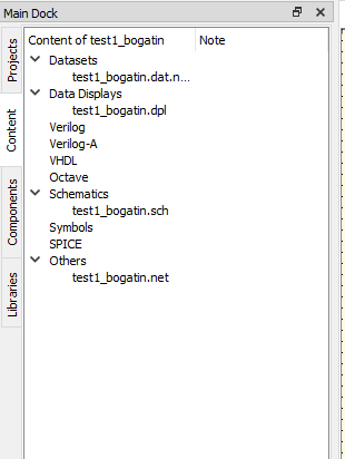
An example project, with its constituent files shown in the Contents tab.
For more information on the types of files which make up a Qucs-S project, and how they are stored, see Understanding File Structure.
Components Tab
This tab can be used to place various components onto a schematic page or display page. Here, “components” is a broad term, which includes:
Ideal passive components
Simulation commands
References to external SPICE files
Diagrams, for graphing/displaying simulation results
Equations
Paintings (non-intelligent, graphics-only elements such as text, lines, rectangles, etc)
Note
All those things, and more, are components. However, specific real-world parts (e.g. “LM334 Current Source”) are NOT part of the Components tab. Rather, these models of real-world parts come from the separate Libraries tab.
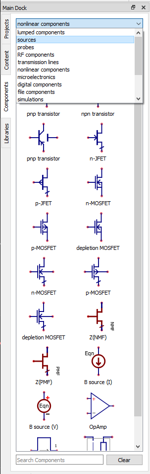
An example of the Components tab.
Warning
The contents of the components tab may change if you select a different simulation backend. Not all components are compatible with all simulation backends.
Component Color Coding
All Qucs-S components can be classified as one of two types:
Universal (Colored Blue): These components are compatible with both Qucsator and ngspice simulation backends. This allows easy simulation of the same circuit across multiple backends, however, the downside is that the full set of special features in the SPICE models may not be leveraged.
SPICE-Only (Colored Red): These components are ONLY compatible with the SPICE-based backends (ngspice recommended). However, the full SPICE model specification is accessible, allowing more advanced customization of device models. This is useful when modeling real-world semiconductor devices, based on manufacturer-provided model parameters. These components will only be visible when a SPICE-compatible backend is selected (such as ngspice).
See the figure below for examples of each component type.
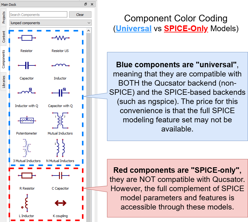
Comparison of “Universal” components (blue color) and “SPICE-only” components (red color).
The same colors remain when these components are placed on a schematic page.
Placing a Component
Select a component category, using the drop-down at the top of the tab. For instance, “Nonlinear Components.”
Find the component you want, either by scrolling or by using the “Search Components” feature at the bottom of the tab.
Single-click the component to select it for placement.
Move your mouse into the main page editor, and single-click to place the component. You can place multiple copies of the component by continuing to click.
When you are done placing the component, push
ESC.
Libraries Tab
This tab contains all the models of real-world parts that are configured with Qucs-S.
For example: where the Components tab might contain an configurable, general model for PMOSFET, this tab contains numerous models for real-world, purchaseable PMOSFETs. This example is shown in the figure below.
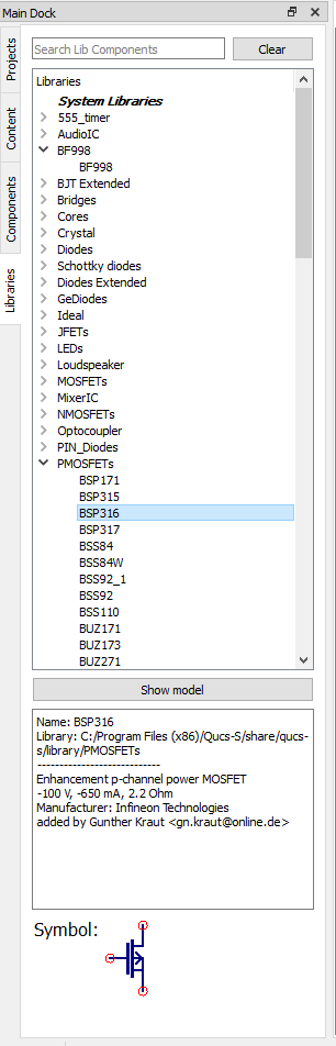
An example of the Libraries tab, with the PMOSFETS category in the standard System Libraries expanded, and the BSS92 part selected. Note that the selected component’s symbol, as well as basic metadata, is shown in the bottom portion of the tab.
Similar to the Components tab, single-clicking on one of the Library items will allow you to place instances of it onto the page.
Within this tab, component models come from 3 places:
System Libraries: These libraries come with QUCS-S upon installation.
User Libraries: These libraries are configurable by the user, and persist across all projects on a given PC.
Project Libraries: These libraries only exist within the active Qucs-S project.
For more information, see the section on Managing Libraries in QUCS-S.
Selecting a Simulation Backend
To select a simulation backend, use the drop-down menu at the top right of the Qucs-S window. Be advised that:
The drop-down menu will only show simulators for which an executable has been found. In other words, it will only show simulators which are both installed on your system and configured properly within Qucs-S (via the Simulation > Simulators Settings dialog).
The drop-down menu will never show the digital-only simulation backends (GHDL and IVerilog). These backends are called via a special object on the schematic page.
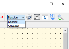
The drop-down menu for choosing your simulation backend. Note that only simulators which are installed and properly configured with Qucs-S are shown in this menu, and the digital-only backends (GHDL and IVerilog) are never shown in this menu.
For more information on which simulation backend is appropriate for your situation, see Choosing a Simulation Backend.
Incompatible Items on Page
Normally, Qucs-S will not allow you to place components on the page which are incompatible with your currently selected simulation backend. For example, if you have ngspice selected in the drop-down menu, the Components tab will only contain items compatible with the ngspice simulator.
However, if you are changing between simulators frequently for your project, you may end up with incompatible components on your schematic. For instance, if you set the project up with ngspice selected as your backend, but you later change to Qucsator or Xyce, some components may not be compatible with the new backend.
In such cases, Qucs-S will warn you of the incompatibility by greying out the component. You can still run a simulation, but these incompatible components will be treated as open-circuits and completely excluded from the simulation. An example is shown below.
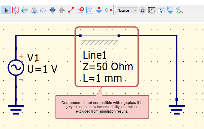
Qucs-S is indicating that the transmission line component is incompatible with the selected simulation backend (ngspice). In this example, this component was placed while Qucsator was selected as the backend, and will not be included in any simulation results produced with ngspice.